 Peter's electronic projects Peter's electronic projects
| part | description |
| C1 |
100nF ceramic capacitor |
| R1 |
10k resistor (1/8W) |
| D1-D4 | 1N4148 diode (optional) |
| S1-S8 |
tact switch, DTSM 61N or similar |
| IC1 | PIC16F630 or PIC16F676 microcontroller, pre-programmed |
| TXMOD |
radio
transmitter module, see text (hardware) |
| B1 |
battery between 2-5.5VDC (check TXMOD specs for valid voltage range) |

| part | description |
| C1 |
100nF ceramic capacitor |
| C2 |
470 uF 6.3V, electrolytic
capacitor |
| R1 |
10k resistor (1/8W) |
| R2 |
10 ohm resistor (1/4W) |
| D1-D4 | 1N4148 diode (optional) |
| D5 |
IR transmitter LED |
| Q1 |
BSS138 or similar N-MOSFET |
| S1-S8 |
tact switch, DTSM 61N or similar |
| IC1 | PIC16F684 microcontroller, pre-programmed |
| B1 |
battery between 2-5.5VDC (CR2032, 3.6V LiIon battery or 3xAA
batteries) |
| please
observe the corresponding address configuration! |
|
 transmitter: no diodes connected |
 receiver: switches all ON |
 transmitter: all diodes connected |
 receiver: switches all OFF |
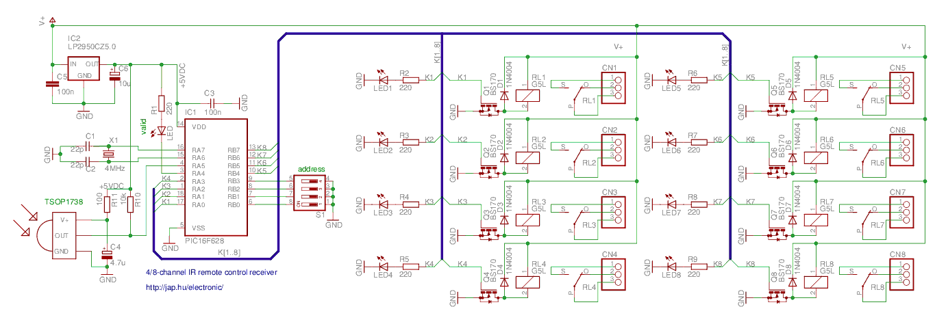
parts list
| part | description |
| C1, C2 | 22pF ceramic capacitor |
| C3, C5 | 100nF ceramic capacitor |
| C6 | 10uF 6.3V electrolytic capacitor |
| CN1-CN8 | PCB terminal block, 3-way (DG301) |
| D1-D8 | 1N4004 diode |
| IC1 | PIC16F627 or PIC16F628 or PIC16F627A or PIC16F628A microcontroller, pre-programmed |
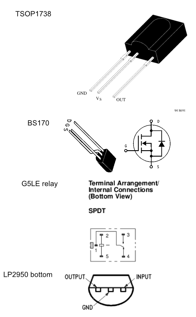
| IC2 | LP2950CZ5.0 voltage regulator |
| LED | 3mm LED (green) |
| LED1-LED8 | 3mm LED (red) |
| Q1-Q8 | BS170 N-channel mosfet transistor |
| R1-R9 | 220R resistor (1/8W) |
| RL1-RL8 | G5LE relay, see text for coil voltage selection |
| S1 | piano DIP switch, 4-way |
| X1 | 4MHz HC49 crystal |
| RXMOD | 3-pin radio receiver module, see text (hardware) |
| please
observe the corresponding address configuration! |
|
| transmitter: no diodes connected |
receiver: switches all ON |
| transmitter: all diodes connected |
receiver: switches all OFF |
parts list
| part | description |
| C1, C2 | 22pF ceramic capacitor |
| C3, C5 | 100nF ceramic capacitor |
| C4 | 4.7uF 6.3V electrolytic capacitor |
| C6 | 10uF 6.3V electrolytic capacitor |
| CN1-CN8 | PCB terminal block, 3-way (DG301) |
| D1-D8 | 1N4004 diode |
| IC1 | PIC16F627 or PIC16F628 or PIC16F627A or PIC16F628A microcontroller, pre-programmed |
| IC2 | LP2950CZ5.0 voltage regulator |
| IC3 | TSOP1738 IR receiver, see text (hardware) |
| LED | 3mm LED (green) |
| LED1-LED8 | 3mm LED (red) |
| Q1-Q8 | BS170 N-channel mosfet transistor |
| R1-R9 | 220R resistor (1/8W) |
| R10 | 10k resistor (1/8W) |
| R11 | 100R resistor (1/8W) |
| RL1-RL8 | G5LE relay, see text for coil voltage |
| S1 | piano DIP switch, 4-way |
| X1 | 4MHz HC49 crystal |
| source
file |
line | meaning |
| enc-042.asm | 25 #define MODE_CH4 | the
device is 4-channel, sending ON/OFF channel codes |
| enc-042.asm |
28 #define MODE_CH8 | the device
is 8-channel,
sending simple codes for channels |
| irmtxv4.asm | 44 pwm_freq EQU d'38000' | the IR transmitter frequency is set to 38000 Hz. This should match the receiver module frequency |
| dec-043.asm | 36
LATCH_MASK EQU 0xff |
select
outputs to be latched. This is a binary mask, one bit per channel.
Other channels will be momentary Example: LATCH_MASK EQU B'00001111' # channel 1-4 are latched, channel 5-8 are momentary |
| dec-044.asm | 38 LATCH_MASK EQU 0xff | |
| mrxv4.asm | 56
#define SKL btfsc 57 #define SKH btfss |
normal decoder logic input is used for the RF receivers (most times) |
| mrxv4.asm | 60
#define SKL btfss 61#define SKH btfsc |
inverse decoder logic input is used for the IR receivers (most times) |
LATCH_MASK EQU B'00001111' sets channels 8-5 to momentary
and
channels 4-1 to latched (toggle) mode. Then use the compiler (MPLAB or
gputils) to
assemble the code.clrf
0x91 ;
ANSEL