This is the rewrite of
the 4/8 channel transmitter software from the PIC16f630 to the
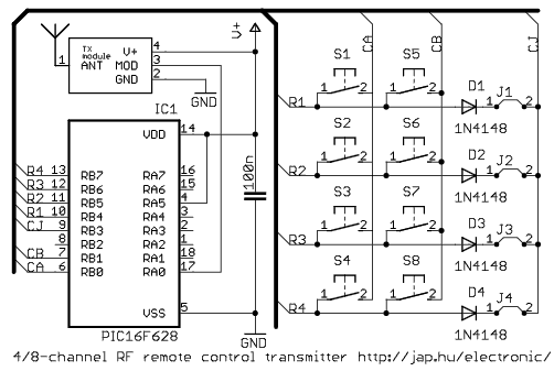
PIC16f627/f628 microcontroller. The 8-channel transmitter has one
button per channel.
The 4-channel transmitter has ON/OFF buttons for controlling four
(latched output) channels. If you need addresses, connect diodes
between
CJ and the R1-R4 pins. Higher supply voltage
results higher transmit power, but V+ range is
2-5.5VDC for the PIC MCU. When V+ is higher than 5VDC, use separate power
for the mcu.
Update on 11/02/2011: the hardware and the software has
been optimized for battery operation (low current consumption). The
two changes are: RA5 (#4) input pin is connected to VDD, and BODEN is disabled
in the configuration word (55 uA).
Download the code for
Select between the 4-channel or the 8-channel version by defining either MODE_CH4 or MODE_CH8, as
described on the
main remote control page.
 Peter's electronic projects