 Peter's electronic projects Peter's electronic projects
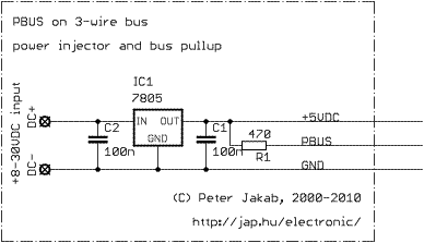 Powering the bus
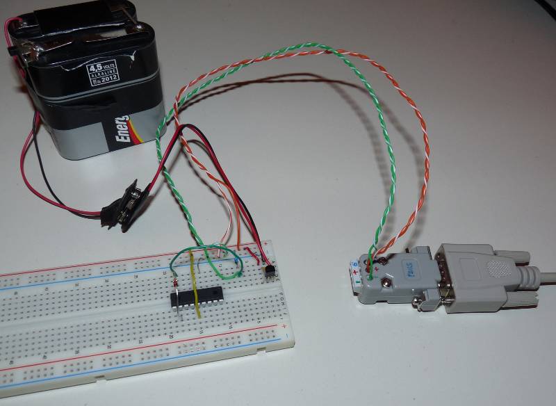
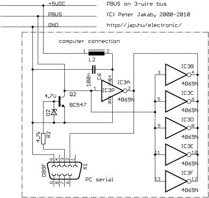 Connecting a computer
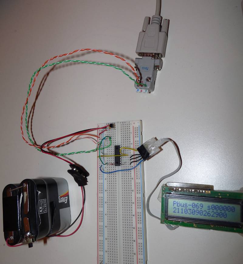
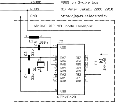 Connecting a microcontroller
| byte offset | bits | name | description |
| 0 | 7-4 | DEVID | destination device PBUS ID (0=master, 1-15=slave addresses) |
| 0 | 3-0 | LEN | optional data length (0 means packet is 3 bytes, no optional data) |
| 1 | 7-0 | CMD | MASTER command or SLAVE response code |
| 2 | 7-0 | DATA[] | optional data, length is given in LEN (LEN=0 means no data) |
| 2+LEN | 7-0 | CHKSUM | packet checksum. All the packet bytes, including the CHKSUM byte summed will result zero |
| dev | cmd code |
cmd parameters |
description |
| M | 5e | CVER | (check node version) |
| S | 60 | ROK <pbus version> [main version] [optional string describing node] | current nodes do not return the optional string by default |
| M | 5f | CPING [optional data] | (test if a node is present and the link is up) |
| S | 6f | RECHO [optional data echoed] | PB12 sources will not echo the supplied ping data back |
| M | 58 | CNOOP | (no operation) |
| S | 60 | ROK | |
| M | 5b | CLAST | (repeat last response) |
| S | (copy of the last response packet sent) | ||
| M | 5c | CRES | (reset statistics counters) |
| S | 60 | ROK | |
| M | 5d | CSTAT | (get PBUS statistics) |
| S | 60 | ROK <e1> <e2> <e3> [optional counters] | The CRES and CSTAT commands can be disabled. |
dev: M=master node (request), S=slave node (response)
Meaning of counters:
| name | description |
| e1 | number of checksum errors |
| e2 | number of good packets received |
| e3 | number of good packets sent for me (not necessarily answered) |
| master node request sent |
textual |
slave node response |
textual |
| 5e (chksum=52) |
CVER |
60 69 10 (chksum=25) |
ROK pbus=69 main=10 |
| 5f de 6f 54 (chksum=ad) |
CPING de 6f 54 |
6f de 6f 54 (chksum=ed) |
RECHO de 6f 54 |
| 5b (chksum=55) |
CLAST |
6f de 6f 54 (chksum=ed) |
RECHO de 6f 54 |
| 5d (chksum=53) |
CSTAT |
60 00 00 04 00 04 00 (chksum=53) |
ROK e1=0000 e2=0004 e3=0004 |
| pbus -s /dev/ttyS0 -d 5 -c 95 5 10 15 20 25 | send a PING command (95 or 5fh) to node ID 5 containing 4 bytes of extra data. Use the serial port at /dev/ttyS0 |
| pbus -s /dev/ttyS0 -d 5 -c 94 | check the code version of the node ID 5 |
cc -o pbus pbus.c| name | version | description | download |
| pbus.c |
v2.4 |
pbus master utility, source code |
pbus.c |
| pbus.tgz |
v2.4 |
pbus master utility, Openwrt package source |
pbus.tgz |
| pbus.mipsel |
v2.4 |
pbus master utility, compiled
little-endian binary for MIPSEL linux platforms (for example, Asus WL-500gP) |
pbus.mipsel |
| pbus.mips |
v2.4 |
pbus master utility, compiled
big-endian binary for MIPS linux platforms (for example, Ubiquiti routerstation) |
pbus.mips |
| name | version | description | download |
| PB628 | 069 | PBUS interrupt driven slave node for devices with a free
hardware UART. Written and tested on 16F628 |
pb628.zip |
| PB88 |
069 |
PBUS interrupt driven slave node for devices with a free hardware UART. Written and tested on 16F88 | pb88.zip |
| dev | cmd code |
cmd parameters |
description |
| M | 54 | PORTA |
(get PORTA I/O bit states) |
| S | 60 | ROK <PORTA state> |
|
| M | 54 | PORTA <PORTA state> |
(set PORTA I/O bit states) |
| S |
60 |
ROK |
|
| M |
55 |
TRISA |
(get TRISA bit states) |
| S |
60 |
ROK <TRISA state> |
|
| M |
55 |
TRISA <TRISA state> |
(set TRISA bit states) |
| S |
60 |
ROK |
| pbus -s/dev/ttyS0 -d5 -c84 |
get PORTA I/O state |
| pbus -s /dev/ttyS0 -d5 -c85 0 |
set all PORTA bits as output |
| pbus -s /dev/ttyS0 -d5 -c84 63 |
set all PORTA I/O bits (A0-A5)
as HIGH |
 and "connecting to
a computer"
and "connecting to
a computer" 
 as shown:
| lcdif pin |
PIC16F88 (DIP18) pin |
PIC16F628 (DIP18) pin |
| 1 (GND) |
5 (GND) |
5 (GND) |
| 2 (EN) |
10 (RB4) |
10 (RB4) |
| 3 (CK) |
11 (RB5) |
12 (RB6) |
| 4 (DA) |
12 (RB6) |
13 (RB7) |
| 6 (+5VDC) |
14 (+5VDC) |
14 (+5VDC) |
gpasm -c main628.asm- link all object files to HEX
gpasm -c lcdlib.asm
gpasm -c pbus628.asm
gplink -o pb628.hex -s 16f628.lkr main628.o lcdlib.o pbus628.o
cc -o
pbus pbus.cpbus -s /dev/ttyS0 -d 5 -c 94
on the computer. The default
node id for the PIC slave is 5. If everything is OK, the PIC e2, e3
counters will increment on the first line of the LCD and the computer
will show the response 60 69 10pbus
-s /dev/ttyS0 -d 6 -c 94
on the computer