 Peter's electronic projects Peter's electronic projects
Add general purpose input/output lines to your computer based
projects. This circuit is a 12 pin digital GPIO interface using the
Microchip PIC18f14k50 microcontroller which connects to an USB host
port. The microcontroller is available in through-hole DIP20 and
SMD packages, too.
NOTE for beginners: PIC18F14k50 is a general
purpose microcontroller which has to be programmed before you can
use it in the actual circuit! Please check out this
link to learn
more.
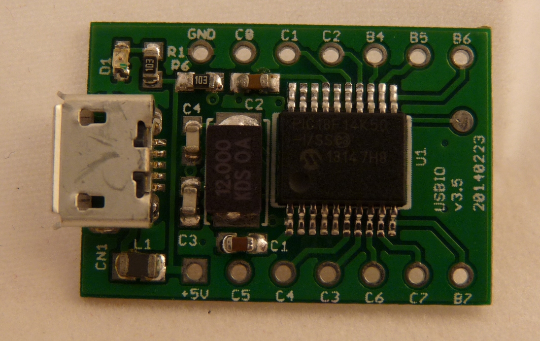
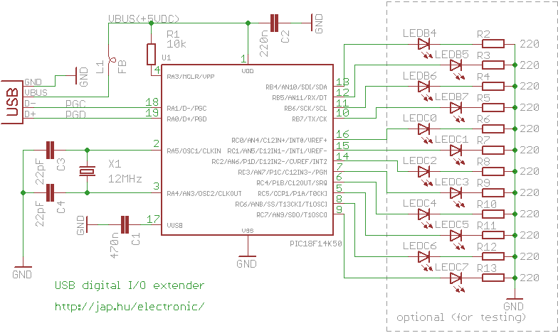
The device is powered by the USB bus. 12 port bits can be set on
a bit-by-bit basis to input or output direction. All LEDs on the
schematic are optional, and are only shown for testing the device.
You can find the USB connector pinouts at http://pinouts.ws/usb-pinout.html
Interested in getting an assembled, pre-programmed, tested board? Check in my Tindie store
A computer, any OpenWrt
router, Raspberry Pi or other Linux development board with an USB
host port can be used to control the GPIO extender. The "controlio"
utility runs on all platforms.
Usage: controlio [options] <command> [value]
Control an USB I/O port

 -d, --device <vendorid>[:productid]
    Select only device(s) with USB vendorid[:productid], default=0x04d8:0xf7c0
 -s, --serial <serial number>
    Select only the device with the given serial number, default=any
 -o, --output <base>
    Set output format. Base x=hexadecimal (16), b=binary (2), d=decimal (10), default=x
 -v, --verbose
    Verbose mode
 -V, --version
    Show program version
 -h, --help
    Show usage and help
The commands are:
| command line |
description |
| controlio getport |
read the digital I/O port
states |
| controlio setdir
<n> |
set the digital I/O port
directions. Use bit 1 to set direction to input, bit 0 to set
direction to output <n> is a 16-bit number |
| controlio setport
<n> |
set the digital I/O port output
states. Sets all output I/O pins. Use bit value of 1 to set output
to HIGH, 0 to set output to LOW <n> is a 16-bit number |
| controlio setbit
<n> |
set the selected digital I/O port
output pins to HIGH. Use bit value of 1 to select I/O pins to
set <n> is a 16-bit number |
| controlio clearbit
<n> |
set the selected digital I/O port
output pins to LOW. Use bit value of 1 to select I/O pins to
clear <n> is a 16-bit number |
Numbers for <vendorid>, <productid> and <n> can
be given in decimal, hexadecimal or binary format. Hexadecimal
numbers are prefixed with '0x', binary numbers are prefixed with
'0b'. Command output base can be also set to hexadecimal with
switch -ox, decimalwith switch -od or binary with switch -ob.
Mapping of I/O port pins, directions to parameter <n> and
buffer output:
|
controlio getport output |
buffer[0] |
buffer[1] |
||||||||||||||
| I/O
pin |
RC7 |
RC6 |
RC5 |
RC4 |
RC3 |
RC2 |
RC1 |
RC0 |
RB7 |
RB6 |
RB5 |
RB4 |
- |
- |
- |
- |
|
controlio setport <n> controlio setdir <n> controlio setbit <n> controlio clearbit <n> |
bit#7 |
bit#6 |
bit#5 |
bit#4 |
bit#3 |
bit#2 |
bit#1 |
bit#0 |
bit#15 |
bit#14 |
bit#13 |
bit#12 |
bit#11 |
bit#10 |
bit#9 |
bit#8 |
Examples:
| command line
example |
explanation |
| controlio setdir
0xffff |
set all I/O pins as
input |
| controlio
getport |
Read the digital I/O
port states. The output is 16 bits long, and is shown in the
selected base (use the -o command line switch). Output ports
usually read back the state they are set to. Input ports read their
externally set state. Command output is: 0xf0ff |
| controlio -od getport |
Read the digital I/O port states.
Same as the previous command, but the output is printed in
decimal:61695 |
| controlio -ob getport |
Read the digital I/O port states.
Same as the previous command, but the output is printed in
binary:0b1111000011111111 |
| controlio setdir
0 |
set all I/O pins as
output |
| controlio setport
0 |
set all output I/O
pins LOW |
| controlio setport 12
or controlio setport 0xc or controlio setport 0b1100 |
set the RC2 and RC3
I/O pins HIGH, other output pins LOW (works only on output
pins) |
| controlio setbit
32768 or controlio setbit 0x8000 or controlio setbit 0b1000000000000000 |
set the RB7 output
pin HIGH, don't change other output pins (works only if RB7 is an
output pin) |
| controlio clearbit
4097 or controlio clearbit 0x1001 or controlio clearbit 0b1000000000001 |
set the RB4 and the
RC0 output pins LOW, don't change other output pins (works only if
RB4 and RC0 are output pins) |
Download drivers and utilities for the GPIO board for Windows, for others. The package contains:
| bin/device_firmware |
the firmware HEX file for the
PIC18F14K50 device |
| bin/host/linux.x86 |
the Linux controlio utility
executable |
| bin/host/openwrt |
the OpenWrt packages for the
controlio utility |
| bin/host/raspberry |
Raspberry Pi binaries for the
controlio utility |
| bin/host/win.x86/driver |
the drivers for using the GPIO
device under Windows |
| bin/host/win.x86 |
the Windows controlio.exe
utility |
| src/device_firmware |
the C18 source code for the
PIC18F14K50 firmware |
| src/host/openwrt |
the source code for building the
OpenWrt package |
| src/host/posix |
the source code for building the
controlio utility for Linux and other POSIX compatible
systems |
| src/host/python |
example code for accessing the
GPIO device from python |
Previous, obsoleted version with assembly
firmware
Program the bin/device_firmware/usbio.hex file with a Microchip
Pickit 2 or Pickit 3 programmer into the chip.
Check operation with "controlio getport". If everything is OK, a
16-bit number read from the I/O port pins is printed. In case of a
"No matching device found..." error the GPIO extender is not found.
The device is identified by the USB vendorid and productid. Check
for the device with lsusb on Linux, cat /proc/bus/usb/devices on
OpenWrt or in the device manager on Windows. Use the "controlio -v
getport" command for troubleshooting.
- install a C compiler and the libusb development
headers
yum install gcc libusb-devel # for redhat/fedora/pidora
apt-get install gcc libusb-dev # for debian/ubuntu/raspbian
- compile the code
cd src/host/posix/controlio
cc -o controlio controlio.c -lusb
- check operation with the command
./controlio getport
- install the OpenWrt SDK on a
computer
- copy src/host/openwrt/usbio into the package directory
- select the usbio package to be built (Utilities->usbio)
from
make menuconfig
- build the usbio package
make package/usbio/compile V=s
- download and install mingw and msys from mingw.org
- copy the file from src/host/posix/controlio/controlio.c to the
c:\mingw\msys\1.0\home\<user> directory where <user> is
your user name
- download and install libusb-win32 from sourceforge
- copy include/lusb0_usb.h from the libusb package to
c:\mingw\msys\1.0\include\usb.h
(if your libusb-win32 version is 1.2.4 or older, then copy
include/usb.h to c:\mingw\msys\1.0\include\usb.h)
- copy lib/gcc/libusb.a from the libusb package to
c:\mingw\msys\1.0\lib
- start the mingw shell from programs->mingw->mingw shell
- compile the code with
gcc -o controlio controlio.c /lib/libusb.a -I/include
- connect the USB device to the computer
- start bin/inf-wizard from the libusb package
- select the connected device from the list, then create and
install a driver for it
- find the executable controlio.exe under
c:\mingw\msys\1.0\home\<user> where user is your user
name
- check operation with the command
controlio getport
yum install pyusb

# or

wget -O pyusb.zip https://github.com/walac/pyusb/zipball/master
unzip pyusb.zip
cd walac-pyusb-*
sudo python setup.py install
The circuit is a full speed (12Mbit) vendor-specific USB device.
It uses only the control endpoint 0, and is controlled by
vendor-specific control requests. If you want to make your own host
interface, the implemented control requests are:
| command name |
setup bmRequestType |
setup bRequest |
setup wValue |
setup wLength |
response |
| GETPORT |
USB_TYPE_VENDOR, USB_ENDPOINT_IN,
USB_RECIP_DEVICE |
0x53 |
unused |
8 |
2 bytes, I/O port states |
| SETPORT |
USB_TYPE_VENDOR, USB_ENDPOINT_OUT,
USB_RECIP_DEVICE |
0x54 |
I/O port states <n> |
0 |
0 bytes ACK |
| SETDIR |
USB_TYPE_VENDOR, USB_ENDPOINT_OUT, USB_RECIP_DEVICE | 0x55 |
I/O port directions
<n> |
0 |
0 bytes ACK |
| SETBIT |
USB_TYPE_VENDOR, USB_ENDPOINT_OUT, USB_RECIP_DEVICE | 0x56 |
I/O port pin selection
<n> |
0 |
0 bytes ACK |
| CLEARBIT |
USB_TYPE_VENDOR, USB_ENDPOINT_OUT, USB_RECIP_DEVICE | 0x57 |
I/O port pin selection
<n> |
0 |
0 bytes ACK |
You can find the explanation of these USB requests (bRequest) and
wValue <n> under "controlling the GPIO
extender"
Please contact me if you need a feature, or have an
idea.