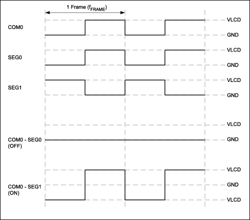
The circuit drives the LCD pins with 50% square waves. Each
segment on this LCD is connected to the COM backplane and a separate
pin. When a pin
is driven in phase with the COM pin, the corresponding LCD segment gets
zero voltage, and is off. When a pin is driven in reverse of
the COM pin, the corresponding segment gets an alternating voltage, and
lights up.
The interrupt routine is called periodically to invert all pins of the
LCD to generate the 50% square wave. The pin states are stored in the
RAM labeled segments_buffer, 5 bytes long. The interrupt also reads the
temperature sensor for the actual values.
The main program gets the temperature value from tc77_ioread, and
calculates the temperature in celsius. All digits of this decimal value
are then converted into the values of the 7 segment of the LCD digits.
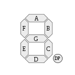
This mapping table is located at the label segtable. For example, the
digit 0 turn on the following digits: F, E, D, C, B, A because it sets
bits as "00111111".


| bit position |
segment |
| bit#7 |
dot |
| bit#6 |
G |
| bit#5 |
F |
| bit#4 |
E |
| bit#3 |
D |
| bit#2 |
C |
| bit#1 |
B |
| bit#0 |
A |
The 16 possible fraction values at the last digit are rounded and
mapped to the last digit at the "lookup_frac" table.
When
the digits in all positions are updated, the "convert_segments"
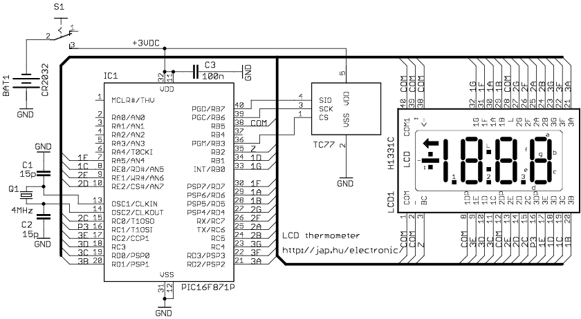
subroutine will map all the segments into the output pins of the PIC.
For example, segment A of the first digit, called 1A is mapped to the
RD6 pin of the PIC.


