Getting character LCDs to work at 3 volts
Generic character LCD modules contain an industry standard HD44780
compatible controller*, which can operate down to 3 volts. But the modules are
usually only specified to work at 5 volts, unless you choose
one designed to operate on 3V.
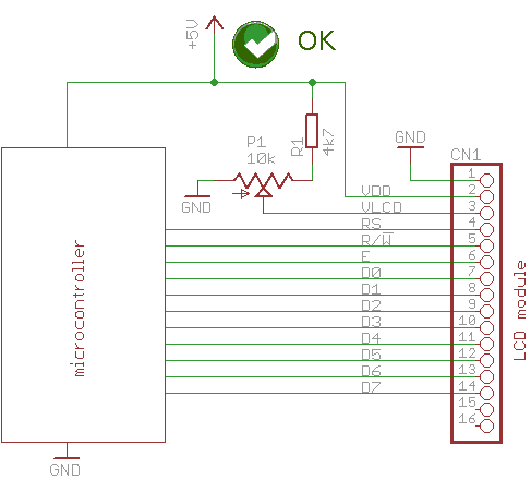
There are two reasons why the modules won't work at 3 volts.
First, the required voltage to drive LCD segments is between 3.8V and 4.4V. This driving
voltage is measured between VDD (pin#2 on pictures) and
VLCD (pin#3 on pictures). Creating this is not a problem when running on 5V - the VLCD
voltage can be adjusted between 0.6V and 1.2V which translates to 3.8V to 4.4V for the LCD (between VDD and VLCD).
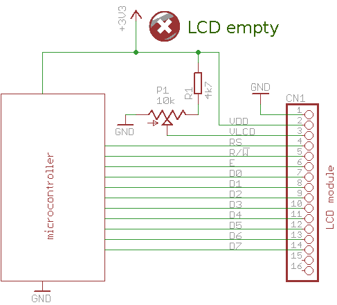
However at 2.7V, 3V or 3.3V the LCD still needs a minimum of 3.8 to 4.4 Volts to show visible segments - this means a negative voltage is required.
To get a suitable LCD driving voltage (min. 3.8V) between VDD and VLCD, the lower side of the adjustment potmeter needs to move to a generated negative voltage (-3V).
Second reason is that the RC oscillator of the controller runs
slower at 3 volts, thus the Rosc resistor on the LCD module may need to
be
adjusted in case the program driving the LCD goes too fast for the LCD controller.
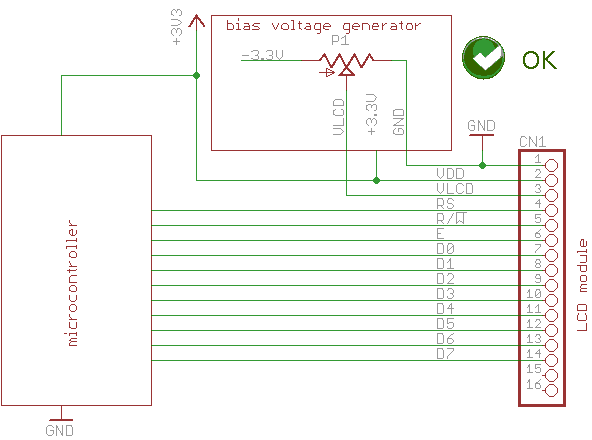
To solve the first problem, the circuit needs a negative voltage to set
the required voltage on the VLCD (pin#3) pin. This is easily
accomplished with a small charge pump which converts the supply voltage
of 2.7-3.3 volts to -2.7 to -3.3 volts.
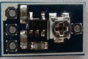
This small, 13 x 9 mm (0.5 x 0.35 inch) charge pump PCB is designed by
me, and it is easy to integrate to an existing 3V circuit.
You can download the Eagle 6 schematics and board layout from github or buy assembled
and tested modules from My Tindie store for $3.
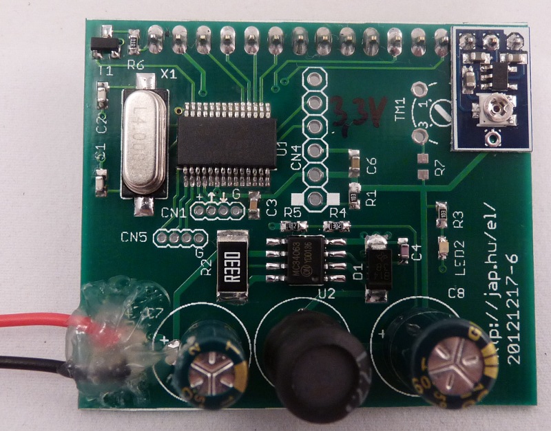
You can add the charge pump to the circuit board to the LCD connector pins #1,
#2, #3, and leave the original contrast trimmer footprint (TM1 on
picture) empty.
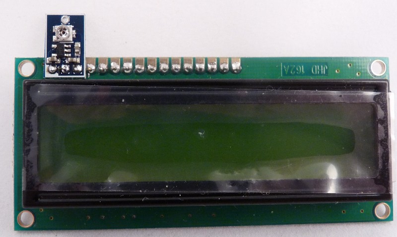
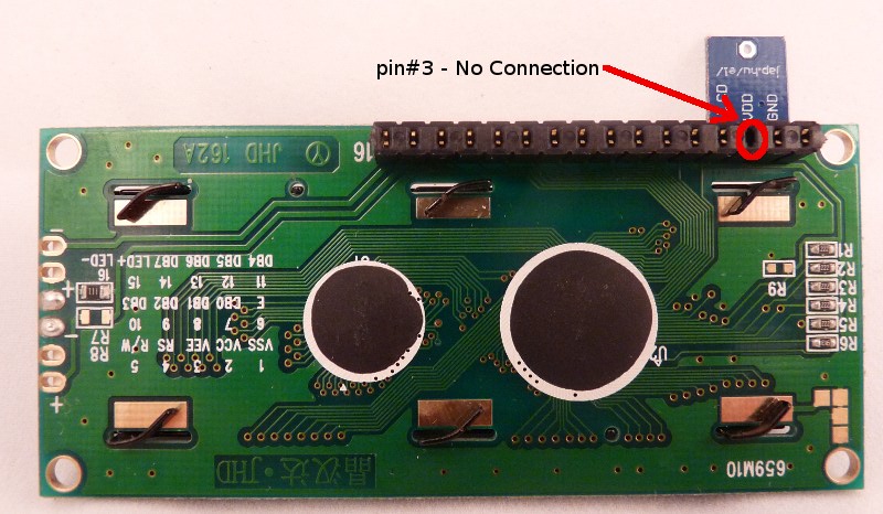
If you don't want to modify the circuit board, you can convert the 5V
LCD to a 3V LCD - just add the charge pump to the LCD module connector pins #1,
#2, #3 and make sure that pin#3 does not connect back to the circuit board.
In either case, make sure that the header is soldered to the LCD or the
circuit board with a small amount of solder in the holes before adding
the bias circuit!
Finding and adjusting the LCD oscillator
For the solution of the LCD clock slowdown, see the next page >.
* generic HD44780 compatible controllers: Samsung KS0066, KS0076, KS0070, Sunplus
SPLC780D, Epson SED1278, Sitronix
ST7066U and others
 Peter's electronic
projects
Peter's electronic
projects