2002/06/16
updated on 2012/09/02
designed by Peter JAKAB
NOTE for beginners: PICs are general purpose microcontrollers which have to be programmed before you can use them in the actual circuit! Check out this link to learn more.
This is a programmable infrared (remote control) transmitter, which can be controlled from a computer serial port. It is capable of sending many remote control formats, including the Philips RC-5 standard. Exact formats with the timing parameter names are shown on the pictures:
The controller will accept commands on a serial port. Settings are: 19200 bps, 8 bits, no parity, 1 stopbit, no flow control (XON/XOFF or RTS/CTS). Commands consist of hex coded bytes and must be written on the port as ASCII characters separated by space, terminated by ENTER (ASCII char 0x0d). The list of commands is here:
| command |
parameters and description |
| SETSTATE | set IR mod output state Setting the mod output HIGH for a long time can result in blowing the IR transmitter LED out! |
| 54 | <state> |
| SETPARAMS | set coding parameters (first format for SENDPDM,
second for SENDRC5) |
| 55 | <ir_T> <head_h> <head_l>
<bit0_h> <bit0_l> <bit1_h> <bit1_l>
<tail_h> <tail_l> |
| 55 | <ir_T> <skipbits> <togglebits> <firstbyte> <rc5tail> |
| SETPWM |
set PWM parameters modify PWM modulation. PWM period time = pwm_T * 1 usecs, PWM duty cycle = dc_T * 0.25 usecs |
| 58 |
<pwm_T> <dc_T> |
| SENDPDM | send ir command header pulse high for T*head_h, low for T*head_l (see transmission format, picture) data bytes transmitted as: bit#0 bit#1 bit#2 bit#3 bit#4 bit#5 bit#6 bit#7 (see DATA format, picture) tail bit is high for T*tail_h, bit0 is high for T*bit0_h, low for T*bit0_1,bit1 is high for T*bit1_h, low for T*bit1_l |
| 56 | <byte> [byte] [byte] ... |
| SENDRC5 | send ir command transmit (16-skipbits) bits: lower (8-skipbits) bits from <firstbyte> then 8 bits from <secondbyte>. The first byte is defined in the SETPARAMS command, second byte is given as parameter data bytes are transmitted as: bit#7 bit#6 bit#5 bit#4 bit#3 bit#2 bit#1 bit#0 bit0 is high for T, low for T, bit1 is low for T, high for T (see transmission format, picture) The bit(s) of <firstbyte> defined in <togglebits> are toggled after the completition of this command. Each <secondbyte> parameter given in this command will transmit a count of (16-skipbits) bits, without updating the toggle bit. The recommended use is to give the same <secondbyte> parameter multiple times to repeat the same code. This is the behaviour when a remote control button is held. The toggle bit is only updated when the command is finished. To send multiple IR codes, issue multiple SENDRC5 commands. |
| 57 | <second byte> [second byte] ... |
ir_T is given in 10 usecs, all other timing values are given in ir_T steps
You can use a terminal emulator program to test out the
circuit (for example minicom on linux, NC terminal on DOS, or
hyperterminal on windows). Line editing is not supported, only the backspace key works.
Download source code and the HEX file here.
The default modulation frequency is defined in the source: pwm_freq
EQU d'36000' - adjust it as required. The default PWM duty cycle is 50%.
| line sent |
explanation |
| 55 38 10 8 1 1 1 3 1 1 | SETPARAMS ir_T=0x38=56d
head_H=0x10=16d head_L=8 bit0_H=1 bit0_L=1 bit1_H=1 bit1_L=3 tail_H=1
tail_L=1 This command will set these PDM parameters: T=56*10=560 usec, header pulse=16T, header gap=8T. bit0 pulse=1T, bit0 gap=1T, bit1 pulse=1T, bit1 gap=3T, tail pulse=1T |
| 56 31 ce 01 fe | SENDPDM 0x31 0xce 0x01 0xfe This command will transmit a header, 32 data bits given as parameter and a tail pulse as seen:  |
| 55 59 2 8 f8 65 |
SETPARAMS ir_T=0x59=89d
skipbits=2 togglebits=8 firstbyte=0xf8 rc5tail=0x65=101d This command will set these RC5 parameters: T=89*10=890 usec, skipbits=2 (16-2=14 bits IR code sent), firstbyte=0xf8, tail gap=101T=89.89 msec |
| 58 1c 1c |
SETPWM pwm_T=0x1c=28d dc_T=0x1c=28d This command will set PWM modulation to period time = 28 usecs (f = 35714 Hz), duty cycle = 28 * 0.25 usecs = 7 usecs = 25% |
| 57 c |
SENDRC5 0x0c This command will transmit a total of (16-skipbits)=14 bits. The first 6 bits are from firstbyte bit#5-#0: 1 1 0 0 0 0. Second 8 bits are <secondbyte>=0x0c: 0 0 0 0 1 1 0 0  |
| 57 c |
SENDRC5 0x0c Repeating a SENDRC5 command will transmit an IR command with the toggle bit(s) updated. bit#3 from firstbyte is toggled from 0 to 1: 1 1 1 0 0 0. Second 8 bits: 0 0 0 0 1 1 0 0  |
| 57 c c c |
SENDRC5 0x0c 0x0c 0x0c Repeating the same <secondbyte> in one SENDRC5 command will transmit the same IR command multiple times, without changing the toggle bit between repetitions. This is the behaviour when a remote control button is held. |
The easiest is if you find the specification of your remote.
Good pages to start are: the
SB projects IR introduction and the HP48 remote
control program page. If you have no success, you need to
measure the signal timings yourself. If you don't have a storage
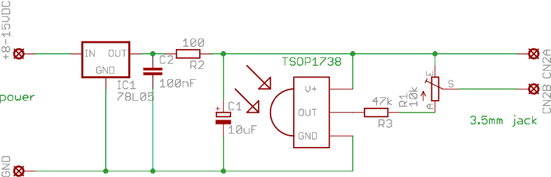
oscilloscope, here is a cheap trick: connect an IR
receiver
module to your soundcard
line input and record the demodulated waveform of the remote with a
sound editor program. Use this small circuit to connect the
receiver module to the sound card line input:
Here is a waveform example for the ITT 3520 video recorder remote,
which is the same waveform used in the previous SENDPDM example:
You can measure the signal length of header, bit0, bit1 and the tail pulse in a sound editor and decode the bits by hand. The yellow bars on the picture show the decoded bits. The last 16 bits contain the button code. The actual code calculated from the bits is "31 ce 01 fe", and will control the video to step one channel up. Another example for the Panasonic remotes POWER button digitized is here:

The encoding scheme is quite similar, with the difference being only in the header/bit pulse/gap times. The capture shows the sequence 02 20 90 00 3d ad.
Recommended link: check dangerous prototypes - it contains lots of IR and remote control related articles and circuits.
The controller and the IR transmitter
parts: V+ input voltage is +8-12VDC, LED1 is an infrared LED. The
preprogrammed microcontroller can be a PIC16F627, PIC16F627A, PIC16F628
or PIC16F628A.

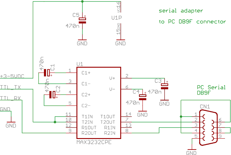
The serial adapter is a voltage level
translator, which converts the TTL voltages to/from RS232 levels
of the serial port. An USB to serial converter board can be used instead of
this adapter. Such adapters are based on PL2303, FT232RL, CP21xx,
CH340, MCP2200 chips. If you choose an USB to serial circuit,