2003/10/25
designed by Peter JAKAB
NOTE for beginners: PICs are general purpose microcontrollers which have to be programmed before you can use them in the actual circuit! Check out this link to learn more.
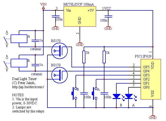
This is a lamp timer capable of operating two separate relay switches. Outputs can be in three (or restricted to two) states: OFF, delayed ON and constant ON. Delayed ON mode is indicated by the LEDs. The source code is easily customizable for your needs: set your desired delay time or disable constant ON state.
alternative operation, if you disable the constant ON mode:
The source code is freely downloadable. This is written for the PIC12F629, but you can easily adapt it to other controllers like the 16F628 or OTP 12C508. The things you should change before use are:
MHZ EQU 4 |
The frequency of the
PIC in MHz (internal 4MHz RC oscillator, OK for the 12F629) |
dly_a EQU .3 * .60 * .100 |
delay in 10 ms (seconds
*100) for relay A the value defined here is 3 minutes |
dly_b EQU .10 * .60 * .100 |
delay in 10 ms (seconds
*100) for relay B the value defined here is 10 minutes |
bt_a_tst1 btfss ct_states, DE_A |
comment out or delete this line to disable turn constant ON for relay A |
bt_b_tst1 btfss ct_states, DE_B |
comment out or delete this line to disable turn constant ON for relay B |
| description | source code | compiled HEX file |
| dual lamp timer 003-2003121130 | lamp.asm | lamp.hex |

| PCB name | Postscript | |
| standard PCB | copper stuffing |
copper stuffing |
Q: I changed the delay values to 30 minutes, but get incorrect delay times
A: The problem is that 30 minutes don't fit into 16 bits. The simplest solution is to increase MHZ to 12, so for the default dly_a, dly_b values you get 9 and 30 mins (the values specified get measured in 30ms instead of 10ms).