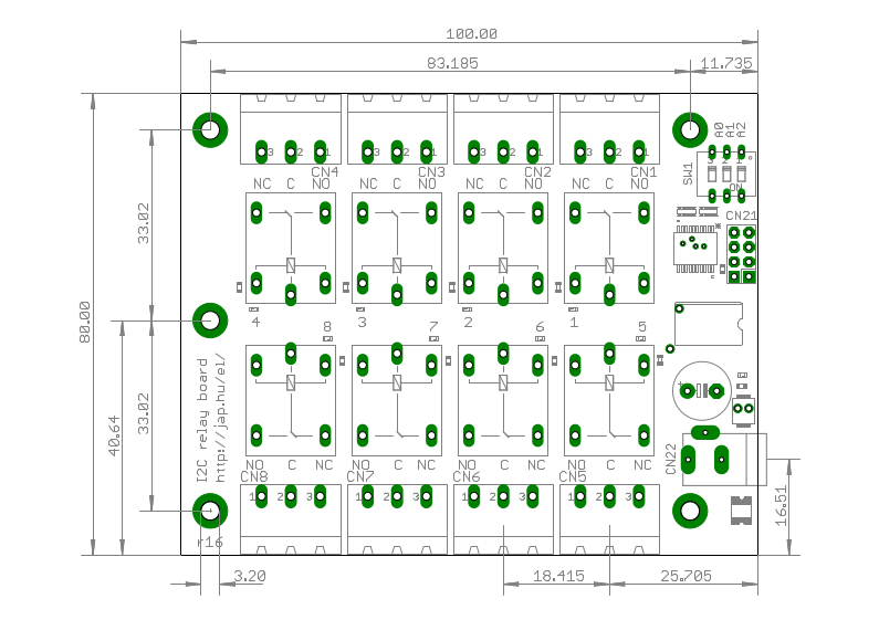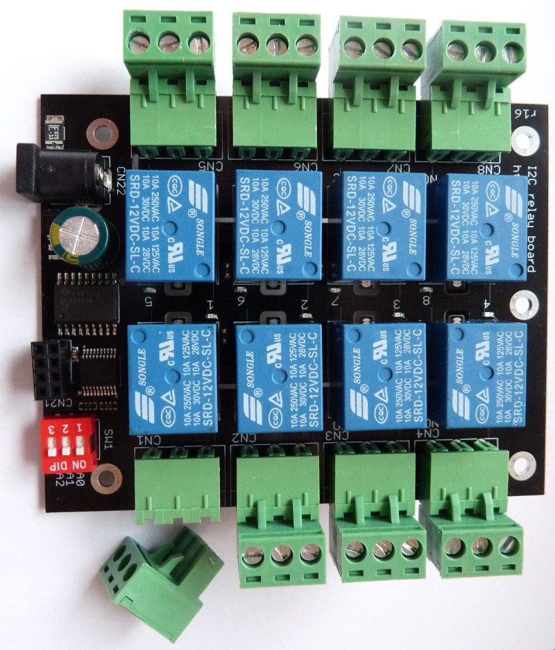
 Board connectors:
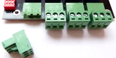
| Board size | 100 x 80 mm (3.94 x 3.15
inch) |
| Logic supply voltage | 3.0-5.5VDC |
| Relay supply input current
required for 5V relays |
635 mA |
| Relay supply input current required for 12V relays | 267 mA |
| Relay contact ratings,
resistive load |
7A 28VDC 10A 125VAC 7A 240VAC |
| Relay contact ratings,
inductive load |
3A 120VAC 3A 28VDC |
| Relay contacts maximum
voltage |
250VAC 110VDC |
| Relay contacts resistance, ON |
100mΩ max |
| Terminal block wire range |
AWG24-AWG12 |
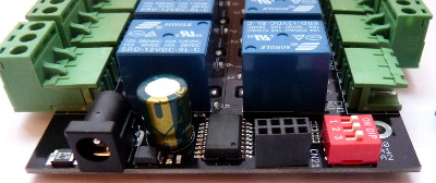
The I2C module board
connects to the master device with connector CN21. The pinout for
CN21 is:
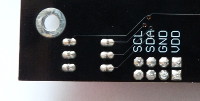
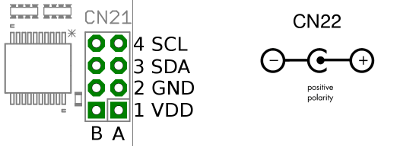
| CN21 pins |
pin name |
| 1A, 1B (square) |
VDD (logic power supply
input) |
| 2A, 2B |
GND (common power supply
ground) |
| 3A, 3B |
SDA (I2C data) |
| 4A, 4B |
SCL (I2C clock) |
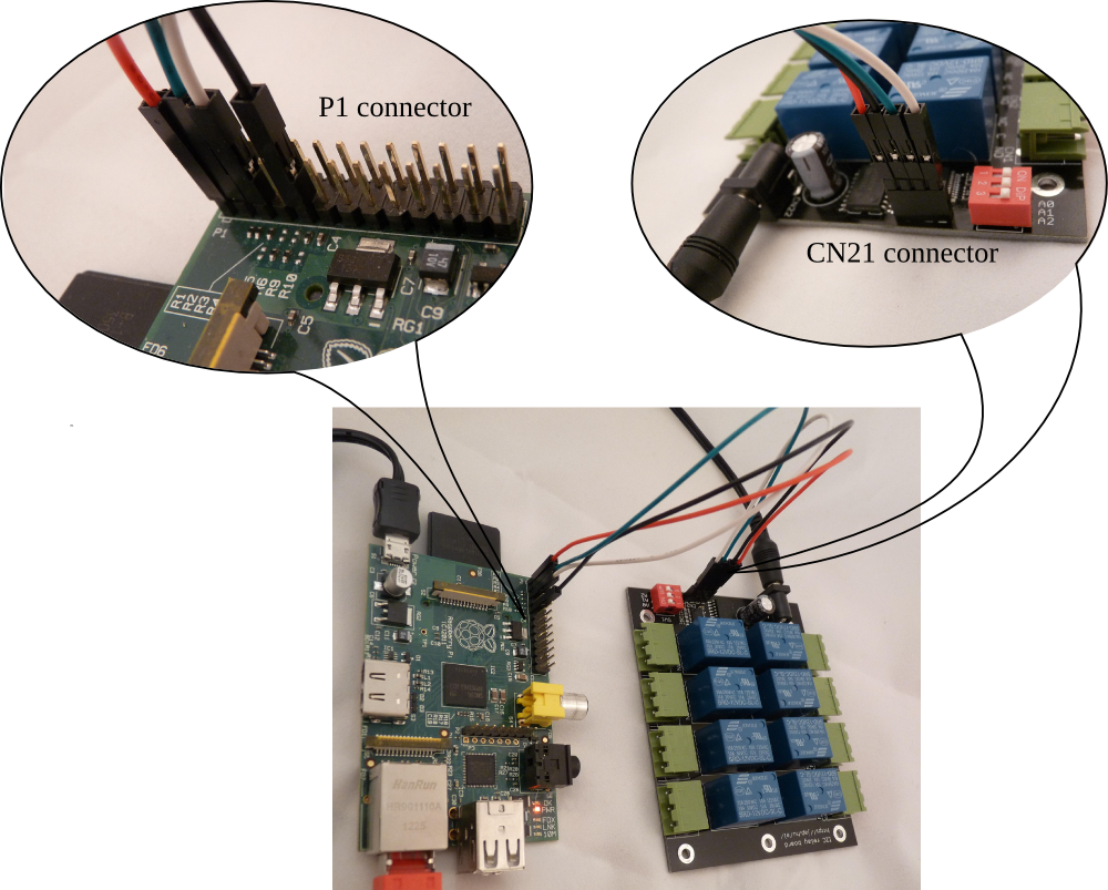
| Raspberry Pi P1 pin | relay module CN21 pin |
pin name |
| 1 |
1 (square) |
+3.3V (logic power supply
input) |
| 9 |
2 |
GND (common power supply
ground) |
| 3 |
3 |
SDA (I2C data) |
| 5 |
4 |
SCL (I2C clock) |
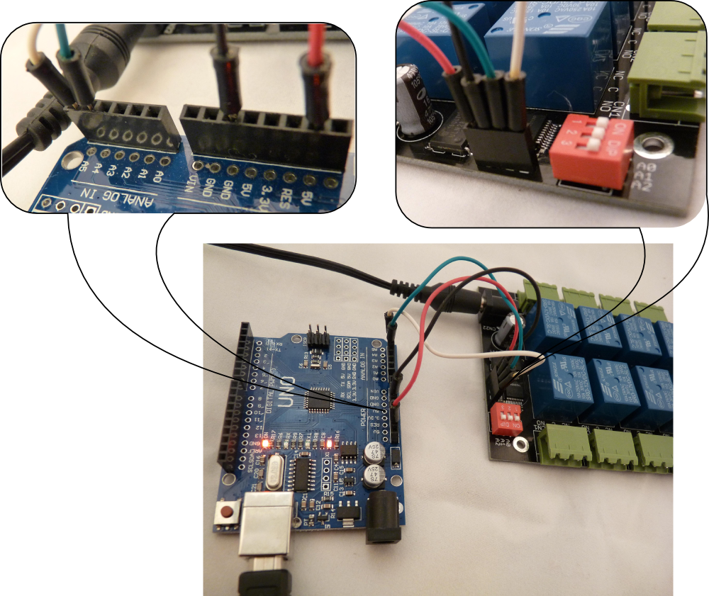
| Arduino
pin |
relay module CN21 pin |
pin name |
| power 5V |
1 (square) | +5V (logic power supply input) |
| power GND |
2 |
GND (common power supply ground) |
| analog 4 |
3 |
SDA (I2C data) |
| analog 5 |
4 |
SCL (I2C clock) |
| bin/linux.x86/relayctl |
relay control utility for
32-bit x86 Linux |
| bin/raspberry/relayctl |
relay control utility for the
Raspberry Pi |
| src/arduino/relayboard_i2c.ino | example source code to control the relay board from an Arduino |
| src/i2c-tools/relayboard_i2c.sh | example shell script to
control the relay board by Linux i2c-tools |
| src/relayctl/ |
C source code for the relay control utility |
| command line example |
explanation |
| relayctl setport 0 |
turn all 8 relays OFF |
| relayctl setport 0b00001100 |
turn relay for CN3 and CN4 ON, all others OFF |
|
relayctl setbit 0b10000000 |
turn relay for CN8 ON, don't change the state of other relays |
| relayctl clearbit 0b01000001 | turn relay for CN1 and CN7 OFF, don't change the state of other relays |
Usage: relayctl [options] <command> [value]The commands are:
Control the relay board
-b, --bus <I2C bus>
Use the given I2C bus to access the relay board, default=/dev/i2c-0
-a, --address <I2C address>
Use the given I2C address to access the relay board, default=0x20
-o, --output <base>
Set output format. Base x=hexadecimal (16), b=binary (2), d=decimal (10), default=x
-v, --verbose
Verbose mode
-V, --version
Show program version
-h, --help
Show usage and help
| command line |
description |
| relayctl getport |
read the actual state of the
relays. Command output is an 8-bit number <n> |
| relayctl setport <n> |
Set all 8 relay
states in one instruction. Use bit value of 1 to turn a relay ON, 0 to
turn a relay OFF <n> is an 8-bit number |
| relayctl setbit <n> |
Turn the selected relays ON. Use
bit value of 1 to select relays to turn ON <n> is an 8-bit number |
| relayctl clearbit <n> |
Turn the selected relays OFF.
Use bit value of 1 to select relays to turn OFF <n> is an 8-bit number |
| relay
contacts |
CN8 |
CN7 |
CN6 |
CN5 |
CN4 |
CN3 |
CN2 |
CN1 |
| bit
position |
bit#7 |
bit#6 |
bit#5 |
bit#4 |
bit#3 |
bit#2 |
bit#1 |
bit#0 |
| bit
value in HEX |
0x80 |
0x40 |
0x20 |
0x10 |
0x08 |
0x04 |
0x02 |
0x01 |
| bit
value in decimal |
128 |
64 |
32 |
16 |
8 |
4 |
2 |
1 |
| bit
value in binary |
0b10000000 |
0b01000000 |
0b00100000 |
0b00010000 |
0b1000 |
0b0100 |
0b0010 |
0b0001 |
| command line example |
explanation |
| relayctl getport |
read the actual state of the
relays. The output value is an 8-bit number, where a bit value of 1
means that the corresponding relay is ON, a bit value of 0 means the
corresponding relay is OFF. Command output is: 0x01 (relay for CN1 is turned ON, others are OFF) |
| relayctl -od getport |
read the actual state of the
relays. Same as the previous command, but the output is printed in
decimal. Command output is: 1 (relay for CN1 is turned ON, others are OFF) |
| relayctl -ob getport |
read the actual state of the
relays. Same as the previous command, but the output is printed in
binary. Command output is: 0b00000001 (relay for CN1 is turned ON, others are OFF) |
| relayctl setport 0 |
turn all 8 relays OFF |
| relayctl setport 12 or relayctl setport 0x0c or relayctl setport 0b1100 |
turn relay for CN3 and CN4 ON,
all others OFF |
| relayctl setbit 128 or relayctl setbit 0x80 or relayctl setbit 0b10000000 |
turn relay for CN8 ON, don't
change the state of other relays |
| relayctl clearbit 65 or relayctl clearbit 0x41 or relayctl clearbit 0b01000001 |
turn relay for CN1 and CN7 OFF,
don't change the state of other relays |
yum install i2c-tools # pidora2. Find the I2C buses on the master:
apt-get install i2c-tools # raspbian
i2cdetect -l3. Scan the buses for the relay module address:
i2c-0 i2c bcm2708_i2c.0 I2C adapter
i2c-1 i2c bcm2708_i2c.1 I2C adapter
i2cdetect -y 0
     0  1  2  3  4  5  6  7  8  9  a  b  c  d  e  f
00:          -- -- -- -- -- -- -- -- -- -- -- -- --
10: -- -- -- -- -- -- -- -- -- -- -- -- -- -- -- --
20: 20 -- -- -- -- -- -- -- -- -- -- -- -- -- -- --
30: -- -- -- -- -- -- -- -- -- -- -- -- -- -- -- --
40: -- -- -- -- -- -- -- -- -- -- -- -- -- -- -- --
50: -- -- -- -- -- -- -- -- -- -- -- -- -- -- -- --
60: -- -- -- -- -- -- -- -- -- -- -- -- -- -- -- --
70: -- -- -- -- -- -- -- --
i2cdetect -y 1The relay module address was found on the i2c-0 bus with address 0x20 (setup with SW1). The bus number (0) and address (0x20) detected will be used in the following steps to select the relay module.
0 1 2 3 4 5 6 7 8 9 a b c d e f
00: -- -- -- -- -- -- -- -- -- -- -- -- --
10: -- -- -- -- -- -- -- -- -- -- -- -- -- -- -- --
20: -- -- -- -- -- -- -- -- -- -- -- -- -- -- -- --
30: -- -- -- -- -- -- -- -- -- -- -- -- -- -- -- --
40: -- -- -- -- -- -- -- -- -- -- -- -- -- -- -- --
50: -- -- -- -- -- -- -- -- -- -- -- -- -- -- -- --
60: -- -- -- -- -- -- -- -- -- -- -- -- -- -- -- --
70: -- -- -- -- -- -- -- --
i2cset -y 0 0x20 0 0 # IODIR5. Set the MCP23008 OLAT register to control the relays: