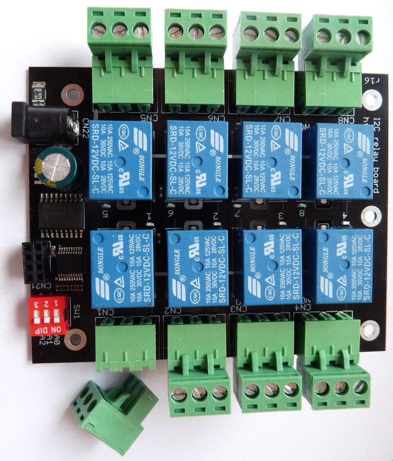
8 channel USB / I2C relay
module board
description
USB
board
|
I2C
board
|
- 8 channel relay module board
with a micro USB
connector
|
- 8 channel relay module board
with an I2C
connection
|
- drivers and control utility for Raspberry
Pi, Linux, Windows and OpenWrt
- comes with the source code
for the driver and the control utility
|
- control utility and example script for Raspberry
Pi and Linux, with source code
- comes with example code
for Arduino
|
- multiple boards can
be
connected to the same host, only limited by the number of ports
available
|
- up to 8 boards can
be connected to each I2C bus
|
- each board can be addressed by its unique serial number, regardless of
which port it was plugged to
|
- each board can be assigned
an I2C address between 0x20 and 0x27 by
the DIP switch SW1
|
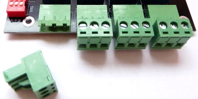
- removable terminal blocks
for easy assembly and disassembly
- relays with SPDT
switch contacts: Normally Open, Common, Normally Closed
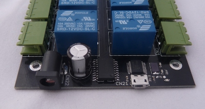
- separate power input
for the relays to avoid glitches on the power lines of the
digital circuits
The relay voltage (CN22) can be 5V or 12V
The logic part (CN21) is powered from the USB port
|
- removable terminal blocks
for easy assembly and disassembly
- relays with SPDT
switch contacts: Normally Open, Common, Normally Closed
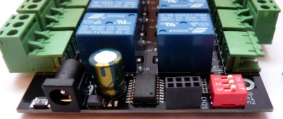
- separate power input
for the relays to avoid glitches on the power lines of the
digital circuits
The relay voltage (CN22) can be 5V or 12V
The logic part can (CN21) can be powered from a voltage between
1.8V-5VDC
|
|
|
|
Board connectors:
- 5.5/2.1mm DC jack
female
connector for relay power input, center positive (CN22)
- micro USB female
connector for logic power input and control
connection (CN21)
 |
Board connectors:
- 5.5/2.1mm DC jack
female connector for relay power input, center positive (CN22)
- 4-pin 2.54mm pitch
connector for logic power input and control
connection (CN21)
|
| Board size |
100 x 80 mm (3.94 x 3.15 inch)
|
| Logic supply voltage |
1.8-5.5VDC |
Relay supply input current
required for
5V relays
|
635 mA
|
| Relay supply input current
required for
12V relays |
267 mA
|
Relay contact ratings, resistive
load
|
7A 28VDC
10A 125VAC
7A 240VAC
|
Relay contact ratings, inductive
load
|
3A 120VAC
3A 28VDC
|
Relay contacts maximum voltage
|
250VAC
110VDC
|
Relay contacts resistance, ON
|
100mΩ max
|
Terminal block wire range
|
AWG24-AWG12
|
USB module
- Connect the USB module board using a micro USB cable between the
host and the connector CN21
- Connect a power supply to the relay
power input jack CN22 (5VDC or 12VDC, depending on the relay voltage of
the board)
- When the board was successfully configured, the red LED status
indicator will turn on
The relay module can be controlled from a Windows/Linux computer,
Raspberry Pi board or OpenWrt
router.
You can use the supplied controlio utility or write your own programs.
Windows requires installing the driver when the board is connected for
the first time.
Using the controlio utility:
Usage: controlio [options] <command> [value]
Control an USB I/O port

 -d, --device <vendorid>[:productid]
    Select only device(s) with USB vendorid[:productid], default=0x04d8:0xf7c0
 -s, --serial <serial number>
    Select only the device with the given serial number, default=any
 -o, --output <base>
    Set output format. Base x=hexadecimal (16), b=binary (2), d=decimal (10), default=x
 -v, --verbose
    Verbose mode
 -V, --version
    Show program version
 -h, --help
    Show usage and help
The commands are:
command line
|
description
|
controlio getport
|
read the actual state of the
relays. Command output is a 16-bit number <n>
|
controlio setport
<n>
|
Set all 8 relay
states in one instruction. Use bit value of 1 to turn a relay ON, 0 to
turn a relay OFF
<n> is a 16-bit
number
|
controlio setbit
<n>
|
Turn the selected relays ON. Use
bit value of 1 to select relays to turn ON
<n> is a 16-bit
number
|
controlio clearbit
<n>
|
Turn the selected relays OFF.
Use bit value of 1 to select relays to turn OFF
<n> is a 16-bit
number |
Numbers for <n> can
be given in decimal, hexadecimal or binary format. Hexadecimal
numbers are prefixed with '0x', binary numbers are prefixed with
'0b'. Command output base can be also set to hexadecimal with
switch -ox, decimalwith switch -od or binary with switch -ob.
Mapping of parameter <n> to relay contacts is:
relay
contacts
|
CN8
|
CN7
|
CN6
|
CN5
|
CN4
|
CN3
|
CN2
|
CN1
|
bit
position
|
bit#7
|
bit#6
|
bit#5
|
bit#4
|
bit#3
|
bit#2
|
bit#1
|
bit#0
|
bit
value in HEX
|
0x80
|
0x40
|
0x20
|
0x10
|
0x08
|
0x04
|
0x02
|
0x01
|
bit
value in decimal
|
128
|
64
|
32
|
16
|
8
|
4
|
2
|
1
|
bit
value in binary
|
0b10000000
|
0b01000000
|
0b00100000
|
0b00010000
|
0b1000
|
0b0100
|
0b0010
|
0b0001
|
Note: bit#15-bit#8 are not used.
Examples:
command line
example
|
explanation |
controlio
getport
|
read the actual
state of the relays. The output value is a 16-bit
number, where a bit value of 1 means that the corresponding relay is
ON, a bit value of 0 means the corresponding relay is OFF.
Command output is:
0x00ff (all 8 relays are turned ON)
|
controlio -od getport
|
read the actual state of the
relays. Same as the previous command, but the output is printed in
decimal:
255 (all 8 relays are turned ON)
|
controlio -ob getport
|
read the actual state of the
relays. Same as the previous command, but the output is printed in
binary:
0b0000000011111111 (all 8 relays are turned ON)
|
controlio setport
0
|
turn all 8 relays
OFF |
controlio setport
12
or
controlio setport 0xc or
controlio setport 0b1100
|
turn relay for CN3
and CN4 ON, all others OFF |
controlio setbit
128 or
controlio setbit 0x80 or
controlio setbit 0b10000000
|
turn relay for CN8
ON, don't change the state of other relays |
controlio clearbit
65 or
controlio clearbit 0x41 or
controlio clearbit 0b01000001
|
turn relay for CN1
and CN7 OFF, don't change the state of other relays |
Download drivers and utilities for the USB relay board for Windows, for others. The package
contains:
bin/host/linux.x86
|
the Linux controlio utility
executable
|
bin/host/openwrt
|
the OpenWrt packages for the
controlio utility
|
bin/host/raspberry
|
Raspberry Pi binaries for the
controlio utility
|
bin/host/win.x86/driver
|
the drivers for using the relay board under Windows
|
bin/host/win.x86
|
the Windows controlio.exe
utility
|
src/host/openwrt
|
the source code for building the
OpenWrt package
|
src/host/posix
|
the source code for building the
controlio utility for Linux and other POSIX compatible
systems
|
src/host/python
|
example code for accessing the relay board from python
|
Windows driver installation
- Extract the contents of the directory usbio-v3.6/bin/host/win.x86
- Connect the relay board to the USB port
- If your OS is Windows XP or Windows 7:
the computer will ask for a driver – choose the driver.winxp-7 directory
Go to step 8. - If your OS is Windows 8 or Windows 10:
start the Zadig installer found in the driver.win8-10 directory
The installer is signed by “Akeo Consulting”. - The bottom of the installer window should read "1 device found".
If it reads "0 devices found" instead, please check the USB connection of the board and repeat from step 4. - Press the “Install driver” button
- Wait for the message “The driver was installed successfully” to appear
- Start the command line and enter this command:
controlio -v getport - If the message “Matching device found.” is shown, the driver is operational
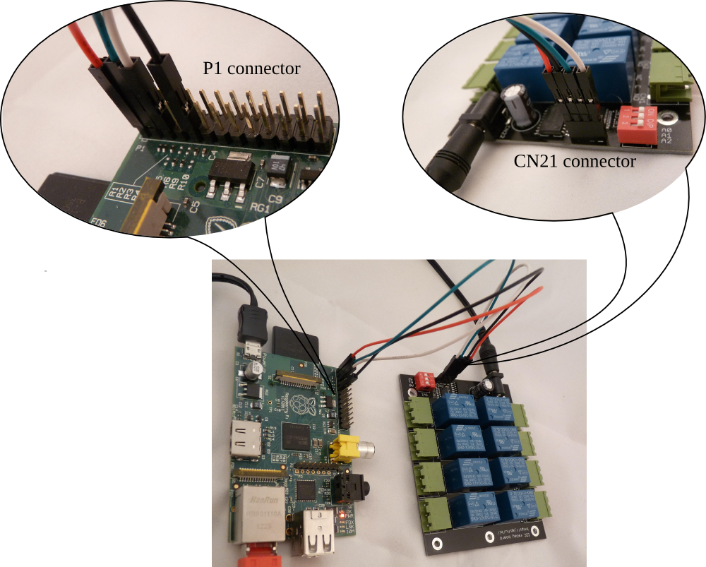
I2C module
- Connect CN21 to the logic
power supply and the I2C bus
- Connect a power supply to the relay power input jack CN22 (5VDC
or 12VDC,
depending on the relay voltage of the board)
The I2C module board
connects to the master device with connector CN21. The pinout for CN21
is:
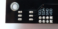
CN21 pin
|
pin name
|
1 (square)
|
VDD (logic power supply
input)
|
2
|
GND (common power supply ground)
|
3
|
SDA (I2C data)
|
4
|
SCL (I2C clock)
|
Connect the relay board to a Raspberry Pi as:
| Raspberry Pi P1 pin |
relay module
CN21 pin
|
pin name
|
1
|
1 (square)
|
+3.3V (logic power supply
input)
|
9
|
2
|
GND (common power supply ground)
|
3
|
3
|
SDA (I2C data)
|
5
|
4
|
SCL (I2C clock)
|
Connect the relay board to an Arduino as:
Arduino
pin
|
relay module
CN21 pin
|
pin name
|
power 5V
|
1 (square) |
+5V (logic power supply input) |
power GND
|
2
|
GND (common power supply ground) |
analog 4
|
3
|
SDA (I2C data) |
analog 5
|
4
|
SCL (I2C clock) |
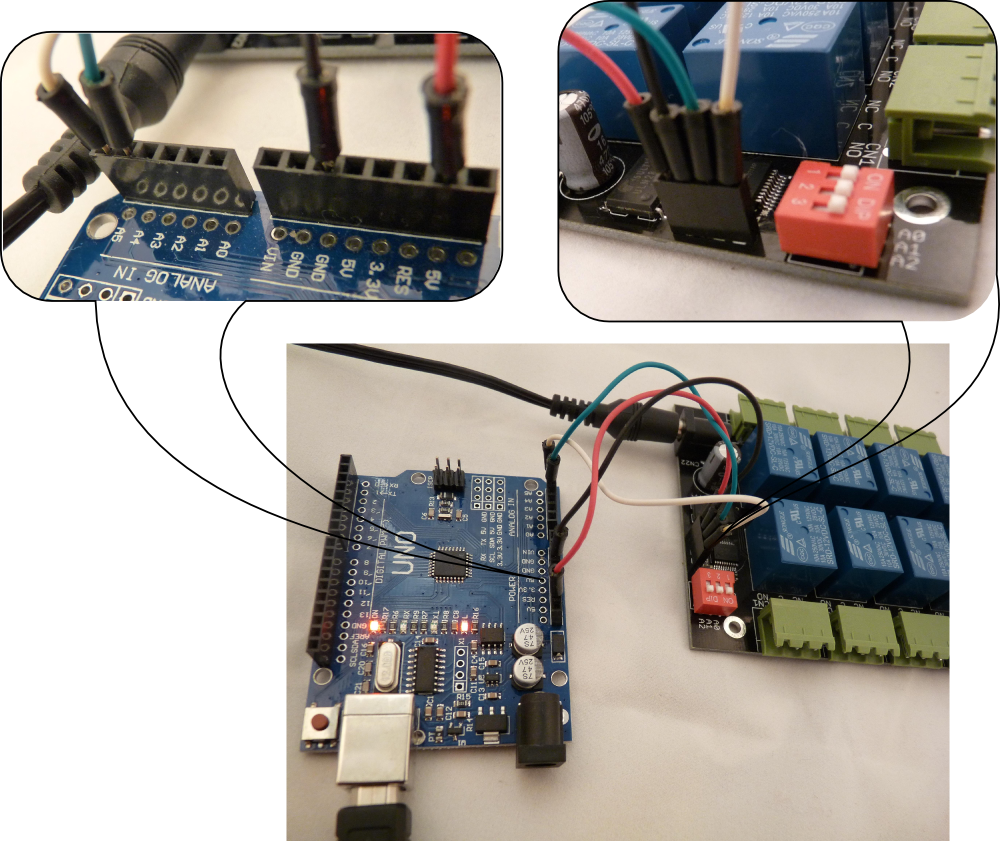
The logic power supply voltage should match the voltage levels on the I2C
bus. The SDA and SCL lines are pulled up to VDD with 47k resistors on
the relay module. The module contains an MCP23008 chip, please
check the datasheet for the details.
Download the
support package with examples and utilities for the I2C
relay board. The package contains:
bin/linux.x86/relayctl
|
relay control utility for 32-bit
x86 Linux
|
bin/raspberry/relayctl
|
relay control utility for the
Raspberry Pi
|
| src/arduino/relayboard_i2c.ino |
example source code to control
the relay board from an Arduino |
| src/i2c-tools/relayboard_i2c.sh |
example shell script to control
the relay board by Linux i2c-tools
|
src/relayctl/
|
C source code for the relay
control utility
|
Example of controlling the relays on a Raspberry Pi board or a Linux
computer:
Using the relayctl utility:
Usage: relayctl [options] <command> [value]
Control the relay board

 -b, --bus <I2C bus>
    Use the given I2C bus to access the relay board, default=/dev/i2c-0
 -a, --address <I2C address>
    Use the given I2C address to access the relay board, default=0x20
 -o, --output <base>
    Set output format. Base x=hexadecimal (16), b=binary (2), d=decimal (10), default=x
 -v, --verbose
    Verbose mode
 -V, --version
    Show program version
 -h, --help
    Show usage and help
The commands are:
command line
|
description
|
relayctl getport
|
read the actual state of the
relays. Command output is an 8-bit number <n>
|
relayctl setport <n>
|
Set all 8 relay
states in one instruction. Use bit value of 1 to turn a relay ON, 0 to
turn a relay OFF
<n> is an 8-bit
number |
relayctl setbit <n>
|
Turn the selected relays ON. Use
bit value of 1 to select relays to turn ON
<n> is an 8-bit
number |
relayctl clearbit <n>
|
Turn the selected relays OFF.
Use bit value of 1 to select relays to turn OFF
<n> is an 8-bit
number |
Numbers for <n> can
be given in decimal, hexadecimal or binary format. Hexadecimal
numbers are prefixed with '0x', binary numbers are prefixed with
'0b'. Command output base can be also set to hexadecimal with
switch -ox, decimalwith switch -od or binary with switch -ob.
The mapping of <n> to relay contacts is:
relay
contacts
|
CN8
|
CN7
|
CN6
|
CN5
|
CN4
|
CN3
|
CN2
|
CN1
|
bit
position
|
bit#7
|
bit#6
|
bit#5
|
bit#4
|
bit#3
|
bit#2
|
bit#1
|
bit#0
|
bit
value in HEX
|
0x80
|
0x40
|
0x20
|
0x10
|
0x08
|
0x04
|
0x02
|
0x01
|
bit
value in decimal
|
128
|
64
|
32
|
16
|
8
|
4
|
2
|
1
|
bit
value in binary
|
0b10000000
|
0b01000000
|
0b00100000
|
0b00010000
|
0b1000
|
0b0100
|
0b0010
|
0b0001
|
Examples:
command line example
|
explanation
|
relayctl getport
|
read the actual state of the
relays. The output value is an 8-bit number, where a bit value of 1
means that the corresponding relay is ON, a bit value of 0 means the
corresponding relay is OFF.
Command output is:
0x01 (relay for CN1 is turned ON, others are OFF)
|
relayctl -od getport
|
read the actual state of the
relays. Same as the previous command, but the output is printed in
decimal.
Command output is:
1 (relay for CN1 is turned ON, others are OFF) |
relayctl -ob getport
|
read the actual state of the
relays. Same as the previous command, but the output is printed in
binary.
Command output is:
0b00000001 (relay for CN1 is turned ON, others are OFF) |
relayctl setport 0
|
turn all 8 relays OFF
|
relayctl setport 12 or
relayctl setport 0x0c or
relayctl setport 0b1100
|
turn relay for CN3 and CN4 ON,
all others OFF
|
relayctl setbit 128 or
relayctl setbit 0x80 or
relayctl setbit 0b10000000
|
turn relay for CN8 ON, don't
change the state of other relays
|
relayctl clearbit 65 or
relayctl clearbit 0x41 or
relayctl clearbit 0b01000001
|
turn relay for CN1 and CN7 OFF,
don't change the state of other relays
|
Using i2c-tools or the example shell script:
1. Install i2c-tools
yum install i2c-tools # pidora
apt-get install i2c-tools # raspbian
2. Find the I2C buses on the master:
i2cdetect -l
i2c-0   i2c             bcm2708_i2c.0                           I2C adapter
i2c-1   i2c             bcm2708_i2c.1                           I2C adapter
3. Scan the buses for the relay module address:
i2cdetect -y 0
     0  1  2  3  4  5  6  7  8  9  a  b  c  d  e  f
00:          -- -- -- -- -- -- -- -- -- -- -- -- --
10: -- -- -- -- -- -- -- -- -- -- -- -- -- -- -- --
20: 20 -- -- -- -- -- -- -- -- -- -- -- -- -- -- --
30: -- -- -- -- -- -- -- -- -- -- -- -- -- -- -- --
40: -- -- -- -- -- -- -- -- -- -- -- -- -- -- -- --
50: -- -- -- -- -- -- -- -- -- -- -- -- -- -- -- --
60: -- -- -- -- -- -- -- -- -- -- -- -- -- -- -- --
70: -- -- -- -- -- -- -- --
i2cdetect -y 1
     0  1  2  3  4  5  6  7  8  9  a  b  c  d  e  f
00:          -- -- -- -- -- -- -- -- -- -- -- -- --
10: -- -- -- -- -- -- -- -- -- -- -- -- -- -- -- --
20: -- -- -- -- -- -- -- -- -- -- -- -- -- -- -- --
30: -- -- -- -- -- -- -- -- -- -- -- -- -- -- -- --
40: -- -- -- -- -- -- -- -- -- -- -- -- -- -- -- --
50: -- -- -- -- -- -- -- -- -- -- -- -- -- -- -- --
60: -- -- -- -- -- -- -- -- -- -- -- -- -- -- -- --
70: -- -- -- -- -- -- -- --
The relay module address was found on the i2c-0 bus with address 0x20
(setup with SW1). The bus number (0) and address (0x20) detected will
be used in the following steps to select the relay module.
4. Set the MCP23008 IODIR register to zero:
i2cset -y 0 0x20 0 0 # IODIR
5. Set the MCP23008 OLAT register to control the relays:
i2cset -y 0 0x20 0xa 0xff # OLAT,
all relays ON
i2cset -y 0 0x20 0xa 0xf0 # OLAT,
turn CN1, CN2, CN3, CN4 OFF, CN5, CN6, CN7, CN8 ON
i2cset -y 0 0x20 0xa 0x00 # OLAT,
all relays OFF